
This post has already been read 2804 times!
Our Murvi Morocco has a 100W solar panel which we found adequate initially but since buying a compressor cool box (Dometic CDF 26) we found after a couple of days off EHU in Brittany last September the batteries were getting a bit low. So it was time to look at fitting an extra panel. The problem is space on the roof is tight.
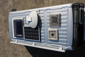
You can see in the image above there is no room for a conventionally shaped panel, like the one already fitted. If we didn’t have a satellite dish it wouldn’t be a problem but we do and the space left to play with is somewhat awkward. The only places left, ignoring above the windscreen (too vulnerable to branches) are the strips of unused roof in front of and behind the roof lights above the kitchen and toilet compartment.
I also looked at whether several smaller panels could be made to fit but there was no satisfactory solution I could find apart from fitting a long narrow panel across the roof of the ‘van.
You can get slimline panels but they are not cheap. This is the one I went for (the 100W version):
http://www.csevolution.net/?q=node/74 This is just wide enough at 410 mm to fit between the current panel and the pair of roof lights, i.e. across the middle of the roof. This still leaves space for a third panel across the rear, above the back doors, if needed later although this will be a slightly trickier fit as it will overhang the rear by a small amount. At 1.6m long it also goes across virtually the full width of the roof.
I bought the panel from these folk: http://www.motorcaravanning.co.uk/shopuk/solar_panels.htm who were very helpful with prompt delivery and their price, at a shade over £200 was half what someone else was selling the same panel for. Having now found out who makes the panel (which I didn’t know until it arrived) I guess it may be possible to buy from the manufacturer directly even if you have to pick it up on a trip to Italy! Of course you can get 100W panels for under a £100 but not of this shape.![]()
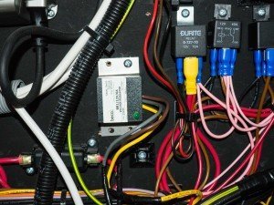
I also needed to change the existing solar regulator from the very basic shunt regulator which was fitted. You can see it in the picture below, it has “beco” written on it and a green light. I had already removed it before realising I wanted a photograph so I refitted it for this shot, which is why it probably looks a bit untidy. The wires were originally all neatly clipped in. Access to all of this is fairly easy and involved the removal of the back of the wardrobe.
I don’t know if this type of regulator is fitted to all Murvis with solar panels but they may be and it is worth having a bit of a discussion about them. The blunt answer is it is a cheap solution but it isn’t by any means the best solution for the control of a solar panel. To understand why it is necessary to understand the relationship between current and voltage for a solar panel. This is probably best explained with a graph but I couldn’t find one which wasn’t copyrighted so I will try and explain it although you can see a graph on this page: http://www.pveducation.org/pvcdrom/solar-cell-operation/open-circuit-voltage
Assuming sunlight is falling on the panel it will generate a voltage and typically, for the sort of panels we are talking about the open circuit voltage, that is the voltage with no load, could be around 22 volts. At the other end of the scale, if you were to short the wires together from the panel (which you can do) it will generate a current at essentially zero volts. Typically this current might be around 4 amps. If you then allow the voltage to creep up the current will remain at about 4 amps for quite a long time, probably only starting to fall off at around 17 volts or so.
Now the way a shunt regulator works is it monitors the battery voltage and when it falls to something around 12.5 volts it will connect the solar panel to the batteries and then as the panel charges the batteries the battery voltage will increase until at something like 14 volts or thereabouts it will disconnect the solar panel. You can see this happening if conditions are right if you look at the meter which shows the charging and battery voltage state when you should see the battery being boosted then left to discharge a while before being charged again as the solar panel kicks in.
The problem with this method is the solar panel is dragged down to the voltage of the battery and this reduces the efficiency of the panel. If I simplify things to make it easier to understand, the panel might produce 4 amps at 12 volts but if allowed to run at 18 volts it might also generate 4 amps – or very close. Power of course is volts times amps so at 12 volts the panel is producing 48W and at 18 volts it is producing 64W, a 50% increase simply by allowing the solar panel to operate at a higher voltage. Of course I have oversimplified things a little to make the sums easier but the principle remains, at higher voltages the panel can run much more efficiently and unfortunately the shunt regulator fitted by Murvi does not allow this.
The solar controllers generally considered the best are called MPPT – or Maximum Power Point Tracking. These work by allowing the solar panel to run at a voltage where it produces the most power. Using the simple example above a shunt regulator would only charge at 4 amps but an MPPT controller might manage 50% more, that is 6 amps.
As I intended to fit a second panel the existing regulator needed to be changed because I planned to wire the panels in series (more of which later) so this was an opportunity to fit a better one. The controller I chose was a Victron 75/15, chosen because it gets good reviews, is very compact and the manufacturer was very helpful in responding to an email I sent them. I bought it from the same company who supplied the panel.
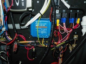
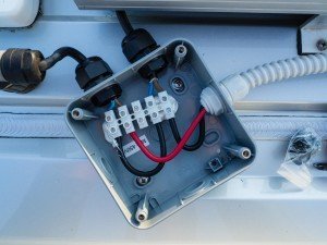
Here is the new controller in position.
And in close up
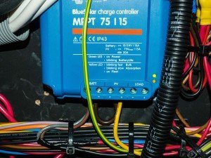
The brown loop of wire you can see connects the two negative terminals for the battery and solar feeds together. The single existing common negative is connected to one of these terminals. I’m not sure if this counts as a bodge – ideally I should have run a second wire but the common wire is very short – it only goes to the big busbar you can see on the right.
Note the load terminals of the controller are not used. This is fine and is what I confirmed with Victron by email – they are a Dutch company but were very helpful. The actual load feeds all come off a fuse box attached to the panel which forms the back of the wardrobe which is fed by thick wires from the batteries. A separate meter senses the battery voltage and current.
The compact size of the Victron controller was a big bonus as space is limited although I still had to reposition one component, a large fuse, but that was all.
To start the fitting I lifted everything up onto the roof to see if it fitted.
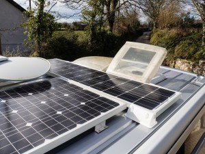
The panel nearest the camera is the existing one and the new one is the long thin one running across the roof of the van beyond it. The picture just shows the panel resting on the supports, no holes drilled at this point. Note the kitchen rooflight is open as I needed to be sure the panel did not get in the way.
Having decided it all fitted, and it only just did, I drank a couple of cups of tea and decided on how to secure everything. I think there are several approaches but given I was working on my own I decided to fit the supports to the roof first then fit the panel. This should work but needed accuracy!
Using 3mm tile spacers I drilled a 2mm pilot hole in the panel frame and 5mm clearance holes in the supports. The tile spacers are needed to ensure the sealant/adhesive id not all squeezed out. The adhesive I used was Sikaflex 512 which seems to be generally recommended for this role. I also used the Sikaflex 205 activator.
In the picture above I’ve fitted 8 * 1″ SS self-tappers (1.25″ might be better in retrospect) into the side frame of the panel. The stand-off distance (gap ![]() ) you can see is due to the tile spacers.
) you can see is due to the tile spacers.
What you should also see in the picture is the angles are all “wrong” because the roof of the van isn’t flat, it is curved which adds an extra fun element. I decided to fit the supports flat on the roof and accommodate the slope in the fit between support and the panel.
The masking tape is there to mark where the support will fit as a guide when putting the Sikaflex on later.
Having marked around all the support I could reach with the masking tape and drilled pilot holes into the roof I took everything off and using one of the supports to show the outline of footprint I put masking tape on the roof around the base of each foot on the bits I couldn’t reach with the panel fitted.
Before fitting the panel I connected the electric cable to it and then ran a layer of Sikaflex around the inside of the masked off area. Having first roughened the paintwork and used the Sikaflex 205 activator.
The roof of course is not only curved it has grooves in it. These I filled with a bit of 6mm Foamex which is the white plastic board frequently used by sign writers. Tile spacers were also used between the roof and the supports.
Once the supports were fitted and screwed down with 8 * 3/4″ SS screws I could fit the panel and after running a bead of Sikaflex around the joint I refitted the screws and tightened them up, using tile spacers again to ensure the mastic wasn’t squeezed out of the joint.
Then the wiring:
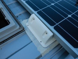
The plan was to cut the existing wire from the original panel and inside a waterproof junction box make the connections to wire the two panels together. It might look a bit odd in the picture, sitting, at an angle, but the problem was there wasn’t a lot of cable between the existing panel and the point where the feed goes down through the roof. So after I had cut this in half and tried everything for size there was really only one position the junction box could go. You can’t see it from the ground so it doesn’t matter really.
The picture above shows the wiring completed but with the cover removed. It is sitting on a couple of blobs of Sikaflex and secured by two screws. The terminal block is also stuck down with Sikaflex. I also drilled a drain hole in the bottom, which you might just see on the right. The glands are also sealed with a bit of Sikaflex as well.
I was slightly disappointed to see the existing cable just looked like 13A flex to me and is a bit thin. Fortunately it isn’t very long as it stops where it enters the vehicle as there is a plug and socket at that point and the cable inside the van is thicker. The brown wire is positive, blue negative and the two panels have been wired in series. When you fit two or more panels you have the choice of wiring them in parallel or series. Wiring in series is considered best for low light levels (UK summers!) so this is what I did. It is also what the instructions for the Victron controller recommended.
When I finally had it all fitted and the sun was shining I used my voltmeter to see what voltage was being produced. Initially I measured a total of about 36V coming from both panels but when I investigated the voltage coming off each panel the result was a surprise. The old panel was producing 22V but the new one just 14V!
The explanation was because of the low February sun a shadow from the satellite dish was across the new panel. Swinging the dish out of the way I suddenly had 22V from each panel. Shading is something solar panels can be very sensitive to, to the extent 5% of the panel being shaded might reduce the output by 50%. This is because the shaded cells act as a significant resistance to the flow of current. Some panels, and the one fitted by Murvi seems to do this, have bypass diodes which reduce the effect, but my new one doesn’t I think but outside the winter this shouldn’t be an issue but it is is worth bearing in mind if you need every drop of power from your panel – ensure there is nothing shading it.
As a test of the new installation I turned the diesel heater on and this drew a current of at least 8A for several minutes while it fired up. I left things to settle down and a little later with the heater running steadily the current consumption on the meter was down to more or less zero, occasionally going up to 0.5A. So at a steady state the panels seemed to be able to keep the heater running despite the weak sun.
At this point the panel voltages were both down to 18V which is the voltage at which they will produce maximum power and where you would expect an MPPT type controller to hold the voltage for highest efficiency.
Turning off the heater the panel voltages quickly went back up to 22V which I guess is almost an open circuit voltage because the controller would have been drawing very little current as the batteries were more or less fully charged with a battery voltage of 13.8V.
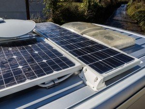
The picture below shows it finished – after a hail storm which is why it all looks damp! The corrugated tube contains the wires from the panel which run to the junction box.
In summary, you can add a second panel as I did and there is even room for a third across the back. Even if you don’t want to add another panel changing the existing controller for a better one should give you more energy from your existing panel. The total cost was about £320, most of which is the panel as it is expensive compared to other 100W panels of more conventional shape. The job is not technically difficult but it does involve drilling holes in the roof, having got up there on some tall steps and working on the electrics. I wouldn’t recommend tackling this yourself unless you feel confident about it. A £200+ solar panel falling off as you drive around a bend wouldn’t be funny!
I used the vehicle for three nights at the beginning of March off EHU, although I drove it each day, but when the sun was shining during the day I saw charging currents of up to 4 Amps so come the summer and a stronger sun we should be able to keep our cool box running more or less indefinitely. If it doesn’t then I will be back here describing how I fitted a third panel!