This post has already been read 3318 times!
Please note: This article describes a fairly major modification involving potentially lethal voltages and very high DC currents which could cause a fire risk. I am publishing it so Murvi owners can see what is possible but I would recommend having the work done professionally unless you are confident enough (or daft enough in my case) to tackle it yourself.
An inverter is a device which turns 12 volt DC into 240 volt AC power. The price of inverters has now come down and so I recently bought this 1500W pure sine model. https://www.amazon.co.uk/gp/product/B06XRCLPD3
This article describes how I fitted it to our Murvi Morocco. A list of the suppliers and components used is given at the end. It is not a cheap exercise as you won’t get any change from £300 and I have 190W of solar panels on our roof, which after several minutes of hair drying are needed to recharge the batteries, so this may not suit everyone though a smaller inverter could be fitted in exactly the same way.
You can spend a lot more than I did on a well known inverter brand such as Victron or Stirling but the Chinese made ones seem to get good reviews. There are two sorts of inverter, pure sine wave and modified or quasi sine wave. Some electrical items, including somewhat curiously electric toothbrush chargers, can be damaged if not run on a pure sine wave inverter and as the price of these has come down this is what I chose, which means we don’t need to worry about what we plug into it.
The inverter instructions say it should be mounted vertically with the fan uppermost though in reality you could mount it more or less in any position as it is never going to be used on full power for more than a few minutes – our two 90Ah batteries won’t last very long pushing out the 125+ amps the inverter will draw at its maximum rating. Amp hour capacities of batteries are based on tests where they are discharged at just a few amps, a very heavy draw of over a hundred amps will probably see them 50% discharged after no more than ten minutes and flattening batteries to below 50% capacity can permanently damage them.
Ideally, an inverter should be mounted as close to the batteries as possible but as I wanted the inverter hidden there was really only one place it could go – inside the space at the back of the wardrobe where all the other electrical stuff is located.
This shows the inverter on the right.
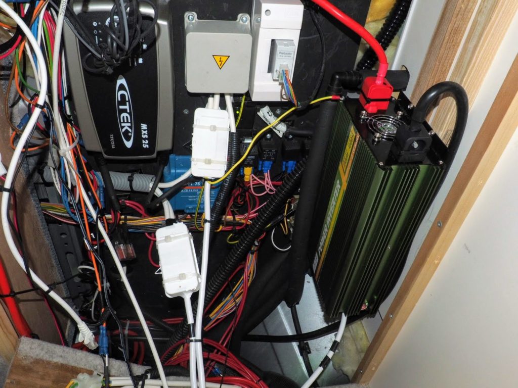
I have fixed it to two wooden battens running vertically up the outside of the bathroom wall. This wall is made of 16mm plywood so provided a solid mounting point. The battens hold it off the wall and leave open a vent to the cupboard under the sink which would otherwise be sealed off if I had mounted the inverter directly against the wall.
You can also see some other changes to the standard wiring in the picture above, particularly the two white junction boxes. To explain why these are necessary I need to describe how the inverter is going to be used.
Our Morocco has five 13A sockets including one in the back of the wardrobe which we have never used. What I wanted the inverter to do was if we were on a campsite with an EHU the 240 volt power would go directly to the sockets, as it does in a standard vehicle. However, if we were not on EHU I wanted the 240 volt output from the inverter to go to the sockets automatically. This is possible if you include a power relay in the wiring to make an automatic changeover.

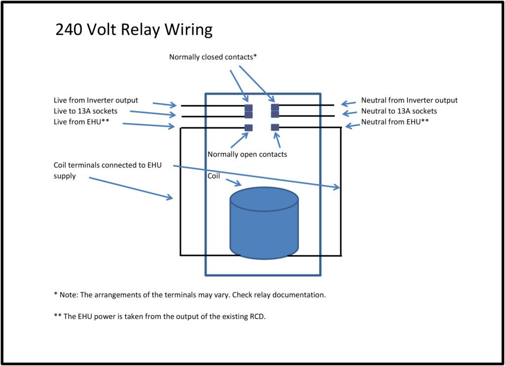
This the relay I fitted, a double pole device from Maplins rated at 240 volts and 10 amps. It has one pair of contacts which are normally closed and another which close when the coil is energised. The EHU power cable is connected to the normally open contacts and the output from the inverter to the normally closed contacts. Two small jumper cables also connect from the EHU terminals to the coil terminals. The cable to the 13A sockets is connected to the third pair of terminals so it will be connected to the inverter normally but when plugged into an EHU the coil will be energised and the sockets will be connected to the EHU power.
Another element I added was an RCD between the inverter and the relay. Fitting an RCD to an inverter may sound a little strange but they are now being fitted as standard to some high end inverters and Victron always recommend one is used. The type of RCD needed is called a mechanically latching one. These do not disconnect the supply if they lose power so it doesn’t need to be reset every time the inverter is turned on.
Finding the cable which go to the sockets turned out to be easier than I feared when I first considered the problem. If you look at this picture again you will see a grey box with an upside down yellow triangle on it. This is basically just a junction box where the EHU power from the output of the existing RCD is split. One cable goes to the fridge, another to the Webasto, one to the CTEK battery charger and two cables go off to the 13A sockets.

Inside the box the cables end in plugs which connect to sockets mounted on a circuit board. To find the socket cables I took a 13A plug and connected the live terminal to the earth – fitting a 3A fuse to be on the safe side! I then plugged this into each socket in turn and using a multi-meter I was able to find which cable had a short between live and earth. This is how I identified the two cables going to the sockets.
The reason for selecting the sockets only is I didn’t want the inverter trying to run the fridge or the Webasto heater on 240 volts.
Having found these two cables I cut them and using junction boxes extended them using a single cable to where the new RCD and power relay were to be mounted.
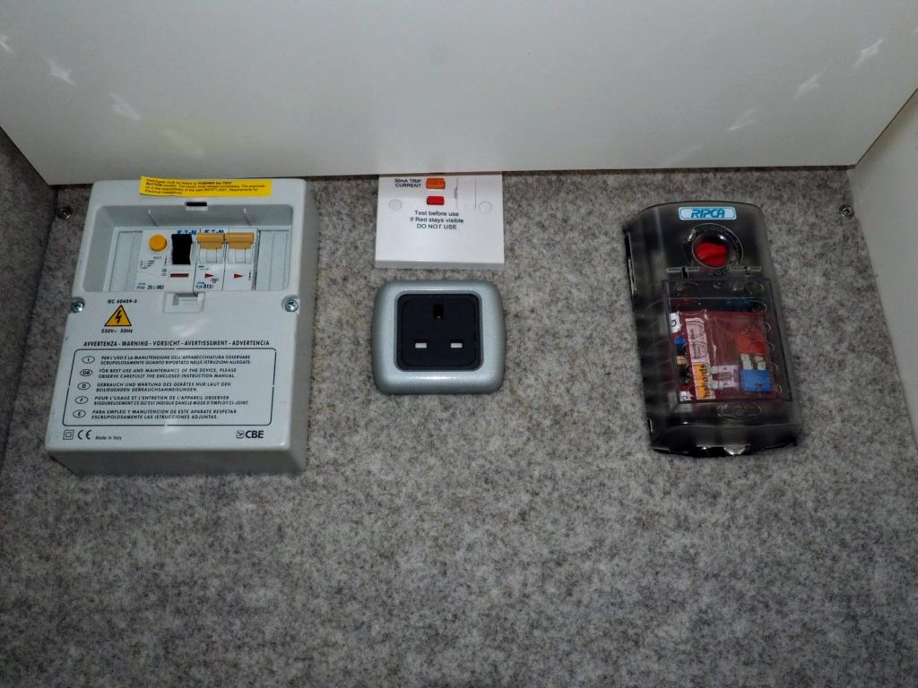
This picture shows the RCD mounted on the panel above the socket in the wardrobe. The shelf in the wardrobe covers the top of it but I simply mounted the shelf a little further forward so access to the buttons is maintained. I could have adjusted the shelf to sit higher but the height it is at now is ideal for the items we store below it. The 13A socket in the wardrobe is not connected to the inverter. This is both because we have never used it and for some reason it has its own separate feed from the RCD so it was just easier not to include it.
OLYMPUS DIGITAL CAMERA
The back of the panel now looks like this.

The relay is fitted inside a 47mm pattress box plus a couple of 10mm spacers behind the new RCD.
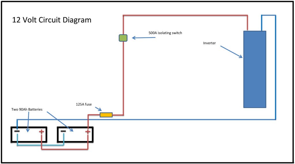
The 12 volt side was less fiddly but given the very high currents which could be generated if there was ever a short circuit, for safety and to ensure there is no current used by the inverter when not in use I fitted a 500A isolating switch under the battery monitor.
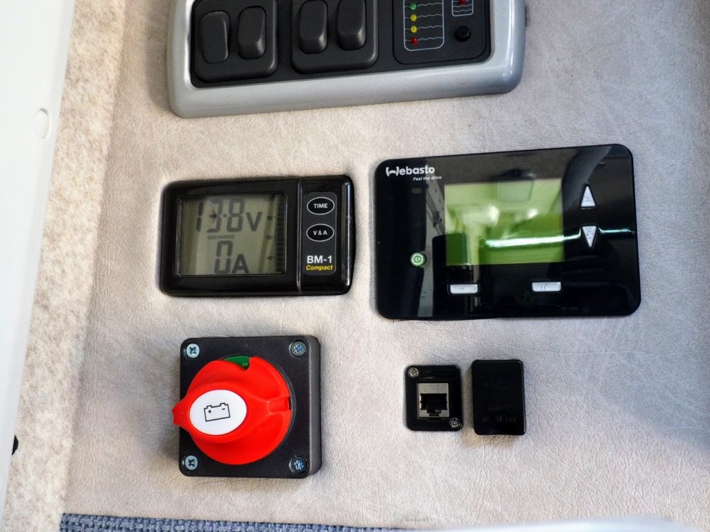
It isn’t exactly discreet but it is easy to get at and use.
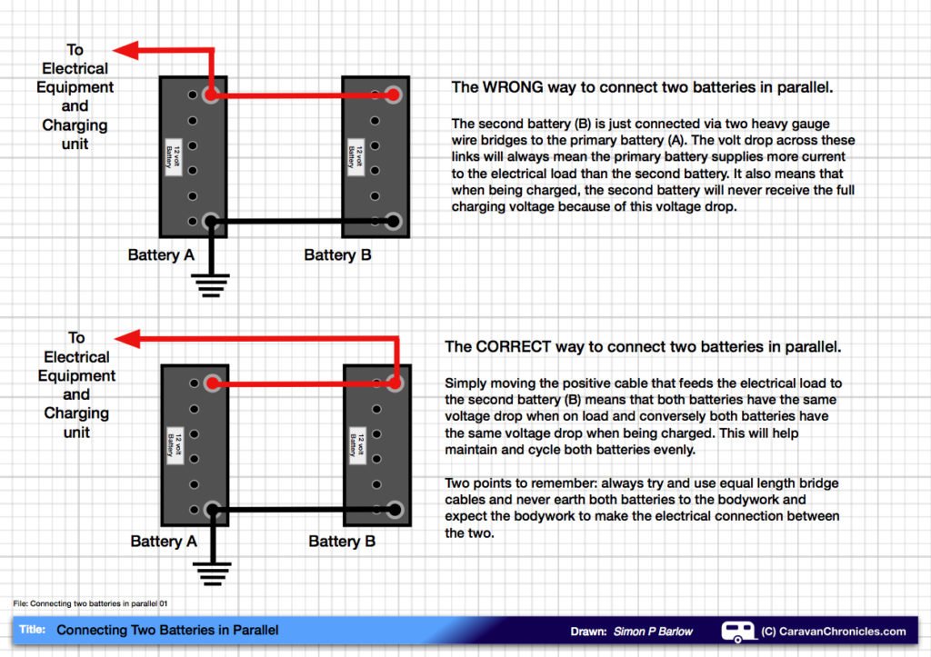
I also added a 125A fuse close to the batteries but not actually in the battery compartment. The fuse rating is its continuous current rating, it will blow at twice this current. To join everything up I used 25mm cables, though on reflection, given the length of the cables needed 35mm cable would be better. Several cables are needed, the black negative cable just runs from one of the battery negative terminals to the inverter but for the red positive several cables are needed. The two battery positive terminals, unlike the negative terminals, are not linked together but each has a separate fused cable which wasn’t what I wanted so I ordered a 35mm cable to link both batteries together. Because of the heavy current which can potentially be drawn by a large inverter it is important to connect the inverter as shown in the lower picture below. Connecting it as the top picture shows will lead to one battery being drained more than the other.
From the battery positive a short cable went through to the compartment to the right where the jack is stored. This may not exist on other Murvi models but on ours this was where I mounted the fuse. Another cable then ran from the fuse to the isolating switch and from there another cable went to the inverter positive terminal.
After testing everything I screwed it all back together and we now have a Murvi with its own private 240 volt supply!
The installation will run a 1200W travel hairdryer though fortunately Mary has short hair and doesn’t run it on its full power setting. I just need to look around for a compact expresso machine now – which was the main reason I wanted to fit an inverter!
The 12 volt circuit is shown below.
The diagram below shows the wiring of the 240 volt relay. A diagram on the side of the actual relay used should show which terminals are the normally open and closed ones as these can vary and may not be in the order shown in this diagram.
When the relay coil is energised, by connecting the EHU cable to a supply, the normally closed contacts will open and the normally open contacts will close. This connects the EHU supply to the sockets. When there is no EHU supply turning on the inverter will provide 240 volts to the sockets.
If the inverter is left on permanently the loss of EHU power say during the night will hardly be noticed as the inverter power will cut in very quickly after the mains supply has failed. This might be useful if a continuous electrical supply is required, say for any medical equipment.
List of components:
Inverter: https://www.amazon.co.uk/gp/product/B06XRCLPD3
Isolating switch: https://www.amazon.co.uk/gp/product/B01NCRKQR2/
Fuse holder: http://www.12voltplanet.co.uk/mega-link-fuse-holder.html
125A fuse: http://www.12voltplanet.co.uk/P00525.html
Cables: https://www.electricalcarservices.com/Battery-Leads-Made-To-Order__c-p-0-0-535.aspx
(These people were very quick (arrived two days after order placed) and the cables very well made.
RCD: http://www.screwfix.com/p/british-general-13a-rcd-fused-spur-white/8250p
Spacer: http://www.screwfix.com/p/schneider-electric-lisse-1-gang-spacer-white/5782j
47mm Pattress box: http://www.screwfix.com/p/schneider-electric-lisse-1-gang-surface-pattress-47mm/2099j
240V Cable: http://www.screwfix.com/p/time-round-flexible-cable-3183y-3-core-1-5mm-x-5m-white/83440
The junction boxes were from Screwfix but I wouldn’t recommend them, they are very flimsy with a useless cable clamp. I was able to sort them using several cable ties but I might replace them in the future.
Power relay: http://www.maplin.co.uk/p/10a-dpdt-miniature-relay-240vac-n09aw
Connectors for the power relay: http://www.maplin.co.uk/p/maplin-intermediate-size-insulated-spade-terminal-female-blue-n35cy
I also fitted 7mm shrink wrap tubing around the connectors to insulate them. http://www.maplin.co.uk/p/7mm-heat-shrinkable-sleeving-1m-bf90x
1200W travel hairdryer: https://www.amazon.co.uk/gp/product/B01KK7Z5GQ